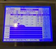
If you are ready to install this screen, you don't need to wait for Stephen to respond to you. I personally like the guy and understand why he is a bit eccentric about the install instructions. There are more than a few cases where clients have not read the instructions thoroughly when he provided them in the package, for whatever reason, hence his desire to make absolutely sure you
get it before proceeding step by step. His bedside manner is, shall we say, a bit acerbic, but he provides an excellent product and knows what he is talking about. I've worked with more than a few musicians over the years that were far more challenging to deal with but came through in the end. Anyway, let's move on.
First thing is getting the case open to access and remove the factory LCD screen. There are other threads here that address this, but I'll hit the highlights:
- Remove the screws securing the faux-wood side panels. Unless someone has changed them out, they should be a #2 Phillips
- You'll need to remove the upper ventilation screen (Doesn't actually ventilate anything). There is in some cases a set-screw on the outside edge on both ends of the screen that needs to be removed, sometimes not. Once the set-screw is removed, take a small to medium sized flat-bit screwdriver to the exposed side edge and gently pries (pry) it up and ease it out of the slot. This will expose five #2 Phillips screws on the panel flange holding the top of the main mixer panel containing the screen.
- Next you will need to gently pries (pry) the scribble strip panel up and out that sits just above the faders. It is held in place with rubber stripping and will ease up and out if you start from the side and work it up...gently. This will expose the #2Phillips screws holding the bottom flange of the mid panel (Can't remember if there are five or six off-hand)
- Lastly, before you can open the mid panel containing the effects and LCD screen, there are two #2 Phillips set screws on the side edge of the panel (About 1/3 of the way down the side edge of the mid panel) that have to be removed before the panel will pivot forward from the top. Do this slowly and the panel hinge will catch at the bottom edge holding it open just past 90 degrees so you can get at the screen area.
Removing the old LCD Screen
- Note in the first picture in the PDF that there is a tan panel sitting on top of the LCD screen that has a red and white pair of wires leading to the upper left of the picture attached to the main mixer board by a plastic (Molex) plug. Unplug it. Next, unplug the connector on the right side of that tan board, undo the two screws holding the tan board in place, and then remove the tan board and set it aside. As indicated in the PDF, the tan board is the Backlight board for the old LCD screen and will not be needed for the new LED screen.
- You will also need to unplug the ribbon cable attached to the old LCD screen by grabbing it by both edges and gently working it out of the Molex connector. It fits snugly, but it will ease out without any trouble if you rock it side to side slightly as you tug. Do this before you remove the four #1 Phillips screws holding the screen in place.
- You can now unscrew the four #1 Phillips screws holding the old LCD screen in place being careful not to drop them behind the main board. (I taped a piece of note/typing paper just below it to catch the screws. )
Installing the new LED Screen
The PDF is pretty self explanatory as far as installing the new LED screen, but there are a couple things I should mention.
- All four screw holes on the new LED screen do not line up with the screw posts on the mixer. Only two of these on one side of the panel will be lined up, the two on the other side will catch the outside edge of the panel to help secure it in place. This creates a tiny offset for the screen in its housing, however does not obscure any part of it. I modified mine by opening the outside edge of the screw holes on the new LED screen with a Dremel tool, which is a delicate operation that I do not recommend unless you are good at this type of thing, which will also void any warranty. My OCD made me do it

- Another important note: Where the red and white leads on the old Backlight board plugged in to the mixer panel, this is where the new LCD red and grey lead depicted in the PDF will plug in. In the PDF it describes removing the Molex housing surrounding the two pins on the mixer and then attaching the plug from the new LED screen. On the newer screens I believe they have the correct plug attached so you can just plug it in without removing the Molex from the mixer pins. If this is not the case, I simply spliced the lug from the old Backlight board onto the new LED screen to avoid potentially damaging the pins on the mixer. I solder spliced mine and shrink wrapped the connections, but a simple splice will work.
- Finally, respecting the brightness attenuator (The Black Trimmer) and the contrast attenuator (The Blue Trimmer): I believe some changes have been madeof late that negate the need to adjust the Blue Trimmer very much at all. But follow the instructions specifically to bring the screen into view if this isn't the case. Also, be sure that the contrast control on the front of the DM console is centered before adjusting the Blue Trimmer. Properly installed, the contrast control on the front of the console will fade the screen to blank white when turned all the way counter clockwise, and to blank blue (Or Black depending on your screen color) when turned all the way clockwise.
- Almost forgot about the ribbon connector. Make sure that you retain the original orientation when plugging it in to the new LED screen. Meaning, keep the blue print face-up so the number one pin matches the number one spot on the Molex connector.
I hope this helps and will offer this up for a sticky with a more detailed PDF when time allows. Intended to do it sooner, but it has been a crazy year for all of us. Also, if I have forgotten anything, please speak up.


